Feather Articulating Ornithopter
How are birds able to travel across multiple continents with days of flight time in non-ideal weather conditions when even the most advanced of small rc aircraft cannot fly for a quarter of that time in great conditions? This is a question that has long fascinated me, and I decided to investigate it by creating an ornithopter, a drone that flies like a bird. I undertook this project with a friend of mine, Aditya Ramachandran, who is now an electrical and computer engineering student at the Olin College of Engineering.

Inspiration
We first started by taking a look at how different types of nature's flying creatures get off of the ground. In particular, we drew a lot of inspiration from the robotic bat project from Caltech and the University of Illinois, as well as this Smarter Every Day video on Macaws in the Amazon Rainforest. We were fascinated by how birds generate lift in mainly two ways: classical airfoil lift and feather articulation.
Classical Airfoil Lift
Birds have a method of generating lift that is pretty similar to our airplanes, that of airfoils moving through a fluid. When the cambered wing of the bird moves forwards through the air, it creates a low pressure zone on top of the wing, and a high pressure zone below the wing. This generates a force upwards: lift. Additionally, the wings of birds are usually angled slightly up from the horizontal, generating lift as it redirects air downwards. This method of generating lift is the same that is used with fixed wing drones.
Feather Articulation
According to the Smarter Every Day video shown to the right, the feathers of the bird's wings fuse together to create an impenetrable membrane on the downstroke, but delaminate to allow air through on the upstroke. This means that the wing exerts more force on the air during the downstroke (wing pushing down) than the upstroke. Due to Newton's second law, for every cycle of upstroke and downstroke, a net lift force is generated. This combined with the classical airfoil lift above is what enables birds to fly so efficiently.

Ask me for anything; I'll always deliver more
The First Prototype
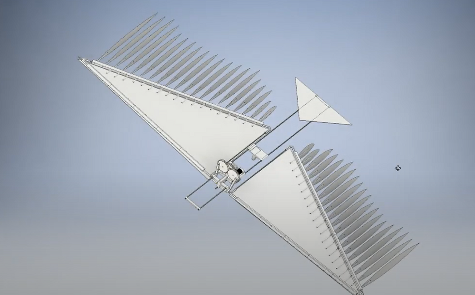
In order to minimize weight, we only wanted three motors on the aircraft: one for the wing and individual feather motion, and two to control pitch and roll. This meant we had to develop one gearbox responsible for both the elliptical motion of the wing and the movement of the feathers. Shown above is our proof of concept, displaying the ability to generate adjustable elliptical motion from one gearbox. It uses a cam gear and a linear reciprocating motion mechanism in order to control movement in two axes. By changing the height of the cam and the radius of the black gear on the side, we can change the amplitudes of the x and y motions, effectively changing the shape that the tip of the wing would trace during flight. As far as feather lamination and delamination, we had originally planned to control the motion of each of the 20 "feathers" using a belt and pulley system that was connected to the continuous rotary motion of the reciprocating elliptical motion mechanism. However, when designing our prototype, we quickly realized that this was not feasible due to the small scale of the feather axes and the amount of "feathers". Because of this, we used the reciprocating linear motion shown in the proof of concept to move a bar back and forth which rotated the linkages attached to the individual feathers. Testing with Computational Fluid Dynamics simulations showed a pressure differential of 4.42 Newtons between the upstroke and downstroke, which meant that we would need approximately 9 flaps per second in order to maintain level flight for a 250 gram ornithopter with a 50 gram payload.
Guiding Hypothesis
We theorized that flying with both of the mechanisms of lift detailed above would be more efficient and more versatile than using only classical airfoil lift generation.
End Results and Learnings
We continuously tuned this prototype until we could reach a controlled glide, although it was very wobbly and did not produce nearly the amount of lift we thought we would reach. For future projects, I learned that 3d printing gears on inaccurate 3d printers can cause mechanisms to break, so it is better to buy them off the shelf or get them prototyped on a more accurate machine. I also learned that the bending stresses in small aircraft can create instabilities that can prevent stable flight. As a high school freshman at the time, it was also great to gain exposure to tools I used in numerous projects after, such as Ansys, CAD softwares, 3d printing, and foam board cutting and sanding.
.png)
Prototyping
We initially started prototyping using two methods: 3d printing and foam board carving. We 3d printed all elements of our gearbox and attached it to a brushless motor. The prototype shown to the right was made with a simplified gearbox that only allows for feather articulation, not for elliptical wing motion. Our wings were made up of 3d printed brackets connected with carbon fiber tubes, and each feather was composed of a thin carbon fiber tube connected to a feather cut out of foam board. It was sanded to smoothly transition from the full thickness of the foam board in the center to zero thickness on the sides. Unfortunately, our gearbox broke shortly after our first test, most likely due to improper tolerances from the 3d printed gears and a poorly sized motor. As we were pressed for time to meet the deadline of this project, we decided to prototype a slightly different implementation of feather articulation where we constrained a Mylar sheet to only be able to bend in a downwards direction so that it bent on the upstroke and did not bend on the downstroke. In this way, the surface area on the downstroke was greater than the surface area on the upstroke, so lift was provided.


