Non-jamming centrifugal engine starter
A dog clutch inspired electric engine starter that is fully FDM printable and never jams.
the problem
We needed an electric starter system for our car engine which was robust and serviceable. The original starter jammed about 10% of the time, and cost about $400 to manufacture with metal printing.
what I did
I performed a scratch redesign of the starter system, using a dog gear mechanism to efficiently toggle between engaged and disengaged states. I iterated on the design through additive manufacturing and testing.
what happened
A starter design that costs under ten dollars to produce, is fully FDM printable, and did not jam in 1.5 seasons of testing.
what I learned
When possible, design to eliminate failure modes instead of mitigating them. The original starter was a throw-in pinion that jammed when the teeth did not align. The new design is a dog gear that is permanently meshed and supported, so it cannot jam. Cheap and simple to prototype designs make analysis of failure modes much easier than overly sophisticated parts.
The mechanism, and why it jammed
The first attempt at this was a metal 3D-printed pinion that had steep threads in its bore, allowing a screw-type spiral to push it into the flywheel when rotated by the starter motor. The pinion was cantilevered, and trying to mesh with an already spinning flywheel, which often caused jams and tooth wear. This design could have worked with sophisticated timing, but the chosen design eliminates this potential failure mode entirely.
Removing the engagement
Because the jam happened at the moment of engagement, I decided to remove the engagement. I replaced the throw-in pinion with a dog gear arrangement: a PETG driving gear that stays permanently meshed with the metal flywheel, continuously in contact and supported rather than cantilevered, with 3 dog teeth on its rear face. The grooved sleeve stayed, but now it only pushes a dog into those teeth instead of slamming gear teeth together. While the material difference between the PETG and the metal flywheel can cause wear, the car runs slow enough and for short enough periods that the gear never wore out across 1.5 seasons of testing.
Before and after
| Old mechanism | metal 3D-printed pinion, thrown into the flywheel at engagement |
|---|---|
| New mechanism | PETG driving gear, permanently meshed, with 3 dog teeth on its rear face |
| Jams before | roughly 10% of starts |
| Jams after | none, across 1.5 seasons of testing |
| Part replaced | cost about $400 |
| Part that replaced it | costs practically nothing, and can be reprinted in-house |
Iterative design
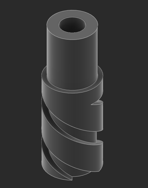
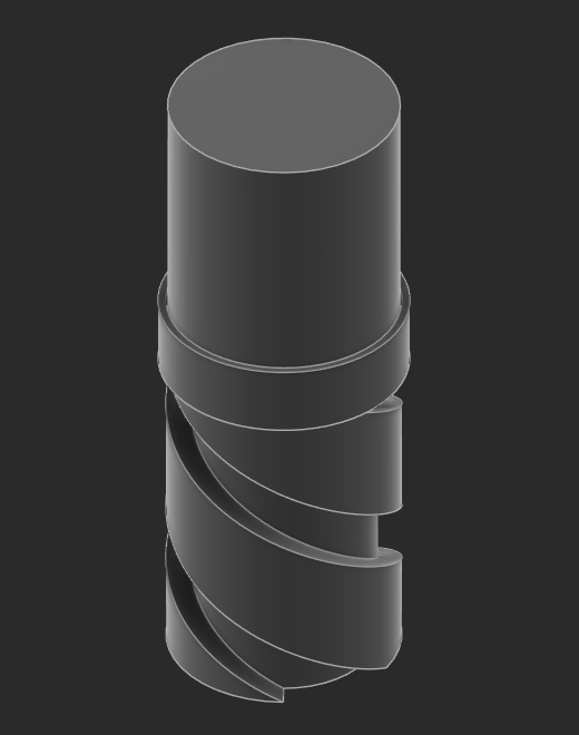
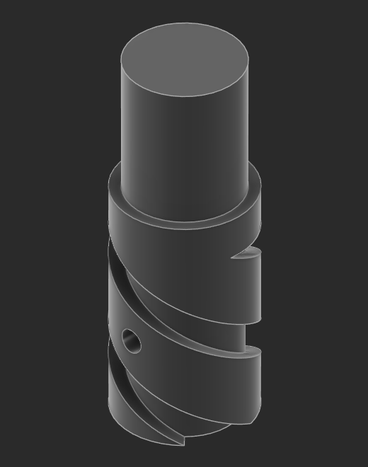
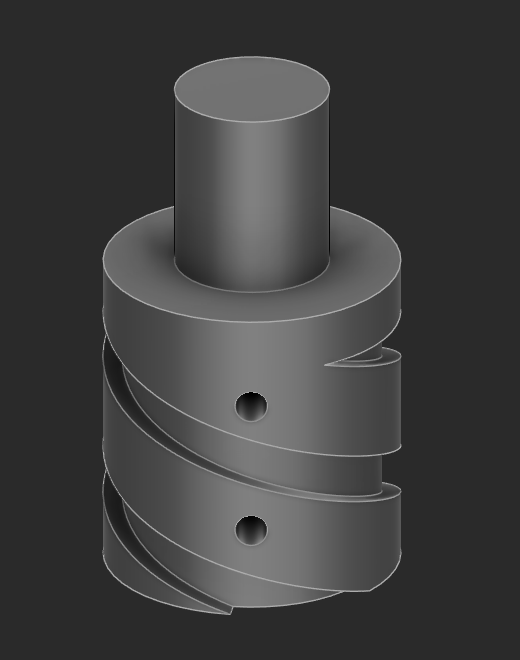
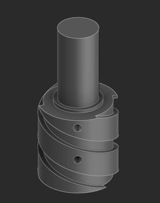
Iterations 1 and 2 of this design used a bearing which was not rated for 30,000 RPM operation, and failed because the bearing seized up. Iteration 3 used a bearing rated for the speed, but the spiral failed in torsion because the grooves introduced stress concentrations. Since torsion scales by the cube of radius, I recognized that we could just make the inner spiral larger, without having to move to metal 3D printing. Iteration 4 added an additional set screw and utilized a d-shaft to more evenly distribute the torsional load. Iterations 4 and 5 were also printed in a different orientation (see below). The final iteration extended the shaft part to fit into a mounting bracket and avoid cantilever vibrations and added a spacer between the inner spiral and the ball bearing of the constantly meshed gear.
The inner spiral, each iteration
Versions of the inner spiral, in the order they were drawn.
Print orientation
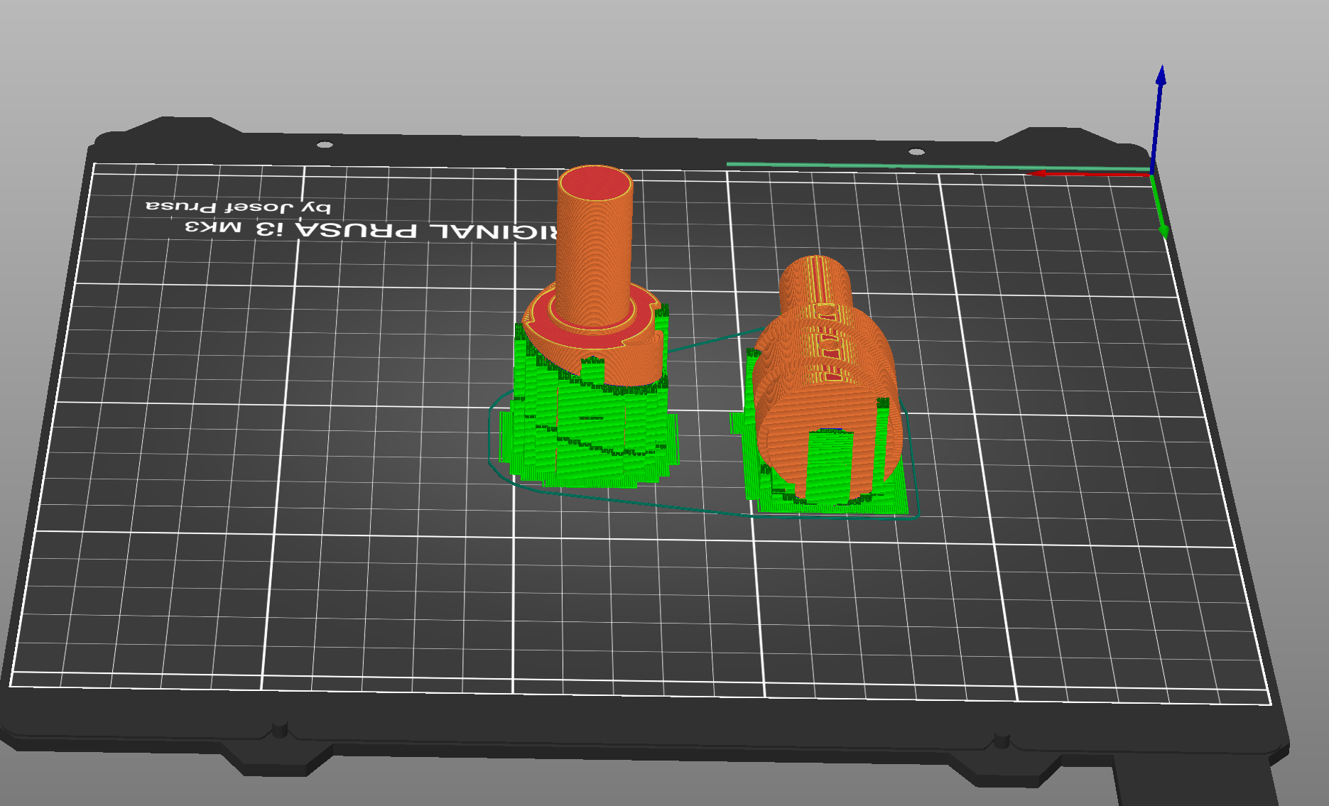
Torsion failure of the PETG material was primarily due to delamination. This was mitigated by increasing the radius, and also changing the printing orientation such that the printing layers were perpendicular to the plane of torsion.